-
湖南迪硕自动化设备有限公司
主营:西门子s7-300代理商,中国西门子代理商,西门子代理商,西门子授权代理商,西门子一级代理商,西门子PLC代理商

湖南迪硕自动化设备有限公司
主营:西门子s7-300代理商,中国西门子代理商,西门子代理商,西门子授权代理商,西门子一级代理商,西门子PLC代理商 9
9

公司的主营产品有:
SIEMENS 可编程控制器
1、 SIMATIC S7 系列PLC:S7-200、S7-1200、S7-300、S7-400、ET-200
2、 逻辑控制模块 LOGO!230RC、230RCO、230RCL、24RC、24RCL等
3、 SITOP直流电源 24V DC 1.3A、2.5A、3A、5A、10A、20A、40A可并联.
4、HMI 触摸屏TD200 TD400C K-TP OP177 TP177,MP277 MP377,
SIEMENS 交、直流传动装置
1、 交流变频器 MICROMASTER系列:MM420、MM430、MM440、G110、G120. MIDASTER系列:MDV
2、全数字直流调速装置 6RA23、6RA24、6RA28、6RA70、6SE70系列
SIEMENS 数控 伺服
1、SINUMERIK:801、802S 、802D、802D SL、810D、840D、611U、S120
2、系统及伺服电机,力矩电机,直线电机,伺服驱动备件等等。主营产品或服务:西门子PLC,西门子变频器,西门子数控系统,西门子伺服电机,西门子人机界面,西门子软启动器,西门子触摸屏,西门子工业以太网,西门子LOGO!,西门子SITOP电源,西门子软件,西门子线缆等!
我们是创新惠及**的企业公民。我们用客户是否成功来衡量我们的创新是否成功。我们不断调整业务组合,以便为全人类共同面临的zui严峻的挑战提供解决方案,从而使我们得以创造可持续的价值。1923年,成立了日本分公司。1937年:在日本侵华,进行南京大期间,建立国际安全区,并出任安全区****,保护了约25万中国人。矢志创新公司不断地成长并开始涉足电气列车和灯泡。1890年,创始人退休,把公司留给了他的弟弟卡尔·海因里希和两个儿子阿诺德·西门子(Arnold von Siemens)以及乔治·威廉·西门子(Georg Wilhelm von Siemens)。1904年:在华业务的迅速拓展,推动西门子在上海设立了*家*办事处,这是西门子在华业务的重要里程碑。追求卓越,是我们在每个业务都将尽力实现的目标。我们根据公司愿景制定这一远大目标,并在其指引下提供优异的质量及追赶客户需求的解决方案。一直如此。1850年,创始人的弟弟,卡尔·威廉·西门子(Carl Wilhelm Siemens)在伦敦设立代表处。
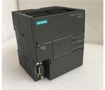
西门子S7-200SMARTCPUST20模块 电 话:(同号)
SINAMICS G120 是一种包含各种功能单元的模块化变频器系统。基本上包括: 控制单元 (CU) 电源模块 (PM) CU 在多种可以选择的操作模式下对 PM 和连接的电机进行控制和监视。通过控制单元,可与本地控制器以及监视设备进行通讯。电源模块的功率范围为 0.37 kW 至 250 kW。 SINAMICS G120 – 优点简介具有很多创新功能 具有用于安全相关机器与系统的 Safety Integrated 功能,能够向输入电源进行再生反馈以节约电能,采用新的冷却方式 组态和调试更加快速 使用 SIZER 和 STARTER 工具;并使用基本操作员面板 (BOP) 和微型存储卡进行数据备份 高效一致的解决方案 通过全集成自动化 (TIA),取得从 SINAMICS 直至自动化级别的一致性
西门子S7-200SMART热电偶输入模块EM AT04 设计和功能 功能模块是能够执行技术任务并因此降低 CPU 负荷的智能模块。 可以提供基于 STEP 7 和 STEP 7-Micro/WIN 的组态工具,用于设置参数。通过具有用户友好性的屏幕进行参数化和试运行。 S7-300 功能模块还可以用在 ET 200M I/O 系统的分布式组态中——以及基于 PC、带有 WinAC 的自动化中。 运动控制基本功能 运动控制功能特点 ? 提供可组态的测量系统,输入数据时既可以使用工程单位(如 英寸或厘米) ,也可以使用脉冲数 ? 提供可组态的反冲补偿 ? 支持**、相对和手动位控模式 ? 支持连续操作 ? 提供多达 32 组运动动包络,每组包络zui多可设置 16 种速度 ? 提供 4 种不同的参考点寻找模式,每种模式都可对起始的寻找 方向和zui终的接近方向进行选择 运动控制的监控
标准型晶体管输出CPU 模块,ST40/S T60 提供3 轴100 kHz高速脉冲输出,支持PWM(脉宽调制)和PTO 脉冲输出· 在PWM 方式中,输出脉冲的周期是固定的,脉冲的宽度或占空比由程序来调节,可以调节电机速度、阀门开度等· 在PTO 方式(运动控制)中,输出脉冲可以组态为多种工作模式,包括自动寻找原点,可实现对步进电机或伺服电机的控制,达到调速和定位的目的· CPU 本体上的Q0.0,Q0.1 和Q0.3 可组态为PWM 输出或高速脉冲输出,均可通过向导设置完成上述功能
PWM 和运动控制向导设置为了简化您应用程序中位控功能的使用,STEP7- Micro/WIN SMART 提供的位控向导可以帮助您在几分钟内全部完成PWM、PTO 的组态。该向导可以生成位控指令,您可以用这些指令在您的应用程序中对速度和位置进行动态控制。PWM 向导设置根据用户选择的PWM 脉冲个数,生成相应的PWMx_R UN 子程序框架用于编辑。运动控制向导zui多提供3 轴脉冲输出的设置,脉冲输出速度从2 0 H z 到1 0 0 k H z 可调。运动控制功能特点· 提供可组态的测量系统,输入数据时既可以使用工程单位(如英寸或厘米),也可以使用脉冲数· 提供可组态的反冲补偿· 支持**、相对和手动位控模式· 支持连续操作· 提供多达32 组运动动包络,每组包络zui多可设置16 种速度· 提供4 种不同的参考点寻找模式,每种模式都可对起始的寻找方向和zui终的接近方向进行选择运动控制的监控为了帮助用户开发运动控制方案,S TEP 7- Micro/WIN SMART 提供运动控制面板。其中的操作、组态和包络组态的设置使用户在开发过程的启动和测试阶段就能轻松监控运动控制功能的操作。· 使用运动控制面板可以验证运动控制功能接线是否正确,可以调整组态数据并测试每个移动包络· 显示位控操作的当前速度、当前位置和当前方向,以及输入和输出LED(脉冲LED 除外)的状态· 查看修改在CPU 模块中存储的位控操作的组态设置
基本订货信息
Configuration of connection for SIMOCRANE CMS to RCMS (Remote CMS)
Overview of the configuration of SIMOCRANE CMS stations and one RCMS station Installation sites and environment
The drive and control technology and the CMS station are located in the electrical room. An industry‑standard Rack PC or a Panel PC can be used as hardware platform. It is recommended that the embedded hardware of the new generation of Rack PC or Panel PC is used, i.e. with no moving parts such as fan or hard drive, using a SSD card instead. In this way high availability of the hardware components can be achieved. The user group mainly consists of service and maintenance technicians. It is possible to call up detailed diagnostics information here, access documentation, circuit diagrams, S7 programmable data blocks, etc. Also the service and maintenance personnel can perform Replay/Playback actions at CMS in the electrical room.
The CMS operator panel in the crane driver cabin is preferably a Touch PC and primarily supports the crane driver in his work. The crane driver receives information on the fault messages, the operating states and operating data, as well as readily understandable diagnostics information. It is only possible to set the operating mode for the crane from the crane driver cabin; and this also applies to activation and deactivation of the technological functions, such as sway control or truck positioning.
The maintenance and system technicians are based here on standby. They require remote access to the CMS systems of the cranes. This requires a standard PC which, as web client, can call up diagnostics and other information from every crane in the terminal. From maintenance building the Replay function can be activated and used on the CMS system. Remote control of cranes can also be performed from the maintenance building as well.
In the case of a network of several cranes and a central data server for long‑term archiving and consolidated evaluation, the RCMS server is located here and any further RCMS operator stations with remote access to the cranes. Administrators, the plant operator, as well as maintenance and service technicians or crane drivers with remote control desks work here. The Replay function can be used via remote station, in web environment, in order to visualize the information from the past. From an RCMS operator station, the terminal operator has a complete overview of the crane terminal and can quickly access an individual crane without the need to be physically on the crane. User groups and functions
The straightforward arrangement provides this user group with the most important information about the operating state of the crane. It is important in a fault situation that the crane driver can detect the cause as fast as possible. He must be able to decide quickly whether they are capable of correcting the fault themselves or whether they require support from a technician. Apart from presenting information, they can also make operational adjustments, i.e. by activating and deactivating options such as SIMOCRANE Sway Control, SIMOCRANE Truck Positioning, etc.
This user group has specific knowledge of the system and can therefore call up more extensive diagnostics information for fast rectification of faults. Maintenance technicians must be able to quickly access the main sources of information that they require for fault rectification purposes. With regard to error messages, maintenance technicians can access specific circuit diagrams and manuals. The Replay function can also be activated and used by this user.
The terminal operator/manager is interested in statistical information and operating data. This user group is provided with this information content in the form of reports and statistics. The Replay function can also be used in the context of remote operation of the crane from a central control desk.
The administrator has access to all authorizations and can set up and manage users. This usually comprises the personnel of the IT department of the plant operator. | 全部关于 System overview 产品与解决方案在线目录与订购系统技术信息服务与支持与合作伙伴服 |